Displaying drawings
CAD Integrator is specially designed to display various types of drawings in the Spaces & Workspaces TSI. These include:
FM (Facilities Management) drawings
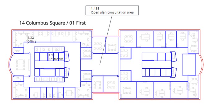
Essentials Edition displays linked FM drawings if you click the CAD Integrator view. See the following example:

FM drawings can be linked to floors in Spaces & Workspaces . Go to Spaces > Floor attributes and populate the FM drawing field.
To link a drawing to a floor, see Linking a floor drawing to a floor.
Constructional drawings
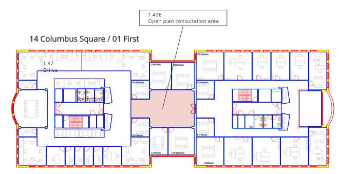
If you enable the Show constructional drawing option on the CAD Integrator drop-down menu, the constructional drawing (.orj file) that is selected in Constructional drawing field in Spaces > Floor attributes is loaded. The constructional elements will become visible in the drawing.
See the following example:

Background image
You can display a background image for a CAD Integrator drawing. To do this, select an image in the CAD background image field in Floor attributes. After selecting the image, resize the image to suit your requirements and save the image by going to the Floors step (in CAD Integrator view) and clicking the Configure background image and Save background image options on the CAD Integrator menu. For more information, see Floor attributes fields.
Transparent drawing
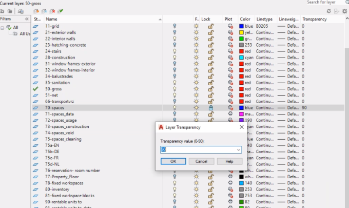
It is possible to display the layers of a CAD drawing as transparent or invisible in the CAD Integrator. This can be done in any AutoCAD tool, by specifying a Layer Transparency value between 0-90:

The visibility of layers will vary depending on the specified value. If the value is set to 90, the layer will be invisible in CAD Integrator after a CAD import.
In the following image, the Transparency of space layer 70-spaces is set to 90 in the AutoCAD tool. After the CAD import, the layers in the drawing will be invisible in CAD Integrator:

The same transparency is applied when you print the CAD drawing with the Save to PDF option.